Central fixed robot
A compact arrangement for machines positioned within one work envelope, provided guarding and operator access remain practical.

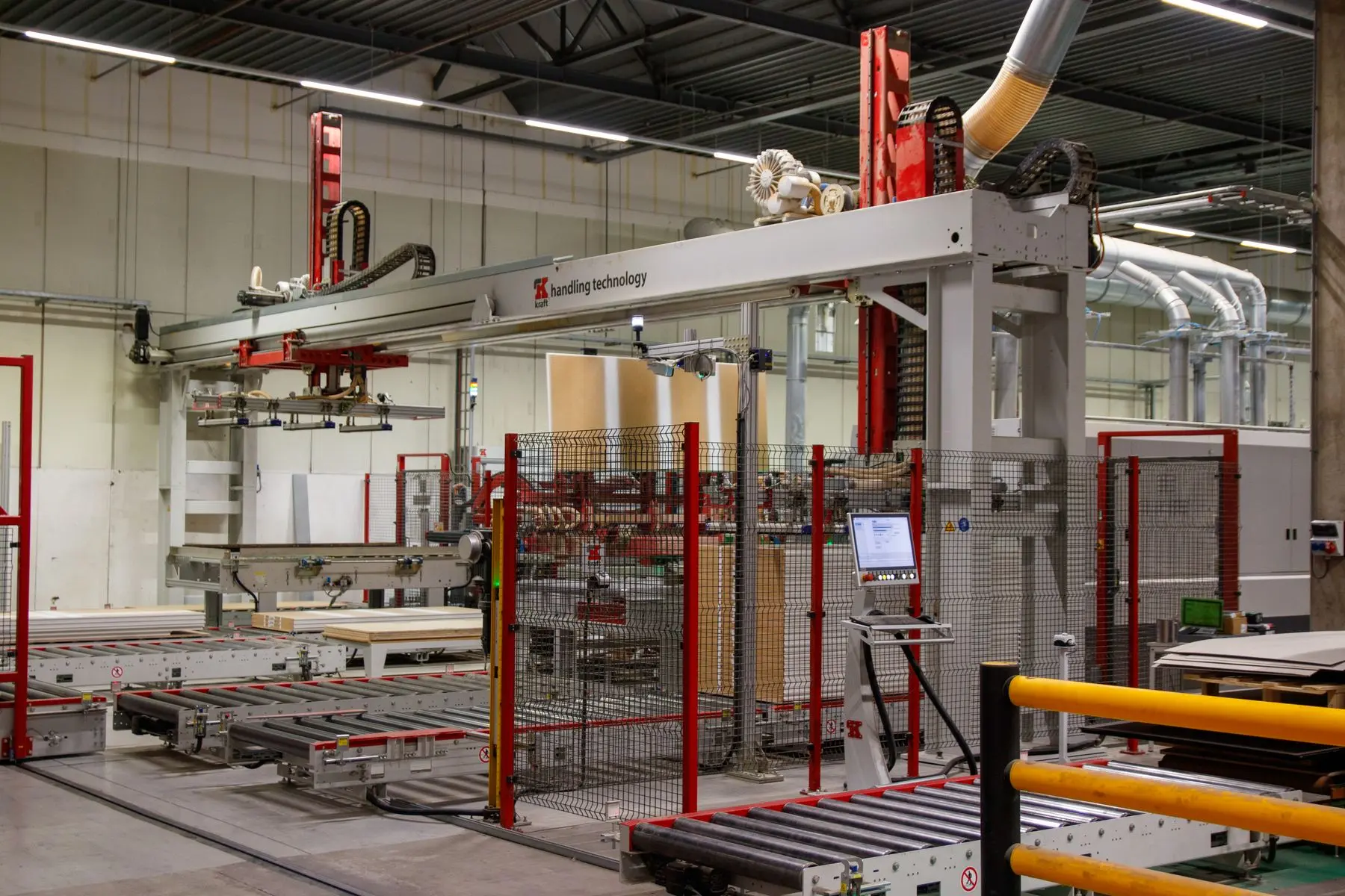
Shared robot cells
Coordinate two or more CNCs or production assets with a shared robot, part-flow strategy and capacity model based on actual cycles, travel, delays and recovery.
Direct answer
Yes, when the machine cycles leave enough time for the robot to travel, open doors, exchange parts, clean workholding, complete checks and recover from normal variation. The answer comes from a capacity model rather than a fixed rule about how many machines one robot can serve.
Two identical machines making one component are different from a mixed cell linking separate operations or part families. Layout, buffers, production priority and fault behaviour must be defined with the robot cycle so a shared system does not become the new bottleneck.
Capacity model
| Input | What to measure | Why it changes the concept |
|---|---|---|
| Machine cycle | Process time for every machine and representative part family. | Defines when each machine will request service and how much robot margin exists. |
| Part exchange | Doors, unloading, cleaning, loading, seating, clamping and robot-clear confirmation. | Shows the real time the machine remains open and unavailable. |
| Robot travel | Paths between machines, presentation, checking and finished-part positions. | Separates a compact central cell from a rail or alternative layout. |
| Manual interventions | Replenishment, inspection, tool change, setup and recovery frequency. | Tests whether the cell still meets output during normal staffed activity. |
| Production mix | Part routes, batch sizes, priorities and changeover sequence. | Determines queue logic, buffers and the risk of mixing part states. |
| Delay allowance | Normal machine variation, confirmation time and credible small interruptions. | Provides usable capacity margin rather than a best-case simulation. |
Cell architecture
A compact arrangement for machines positioned within one work envelope, provided guarding and operator access remain practical.
Extended travel along a row of equipment where rail time, cable management and safeguarded access support the capacity case.
One platform moved between compatible machines at different times, using repeatable docking, services, recipes and validation checks.
A controlled route through machining, cleaning, measuring, marking or a second process with intermediate buffers where required.
Queue logic serves whichever compatible machine becomes ready while maintaining clear raw and finished-part routes.
Layout, controls and capacity are prepared for a later machine without compromising the performance required from the first stage.
Controls and part flow
The controller must know which machines are ready, which operation each component needs and which job has priority. Raw, in-process, finished, rejected and uncertain parts require defined locations so a fault does not create an unidentified component.
Frequently asked questions
There is no fixed number. Machine cycles, robot exchange time, travel, part flow, replenishment and recovery determine whether the robot has enough capacity with suitable margin.
Potentially, yes. Each machine needs a suitable physical and control interface, and the cell controller must coordinate the different ready, cycle, fault and permission states.
No. A rail extends reach but adds travel, cost, access and control considerations. A fixed central robot may be simpler where the machines can be arranged within reach and the layout remains usable.
The design should define whether the robot can continue serving other equipment, where the affected part is contained and how the stopped machine can be recovered safely without losing track of the remaining production.
Prove the shared-cell concept
Include machine positions, current loading steps, batch pattern, inspection frequency and the production priority you need the cell to protect.