Stable machining
Confirm repeatable cycles, workholding, tool life, coolant behaviour and component quality before removing routine supervision.

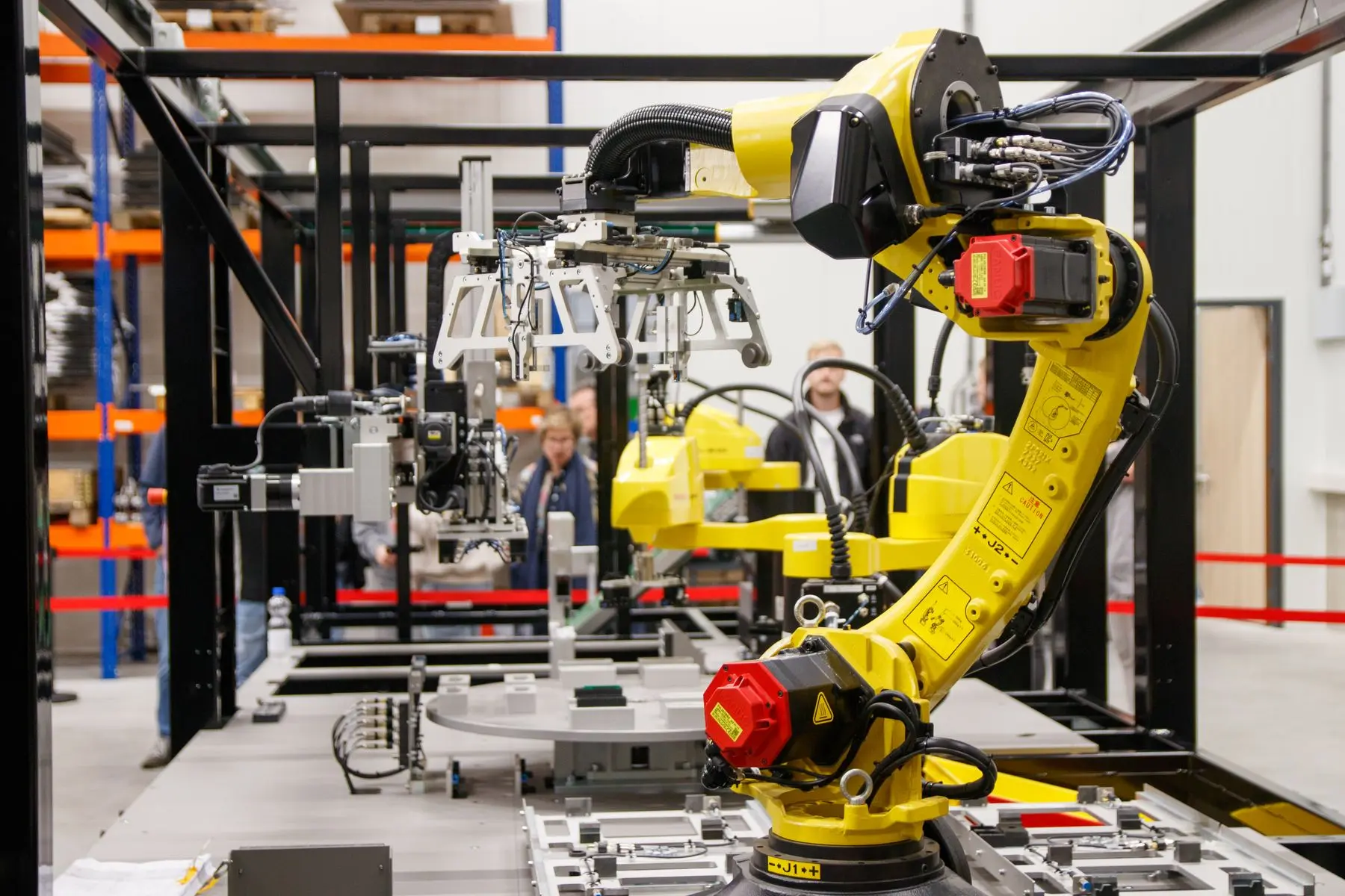
Unattended CNC production
Extend productive hours with a robot or cobot cell designed around part capacity, tool life, swarf, inspection and recoverable faults—not only automatic loading.
Direct answer
Lights-out CNC machining means running a lathe, mill or machining centre for a planned period without an operator continuously present. A machine-tending robot can load and unload components, but the useful unattended window also depends on raw-part supply, finished-part storage, tool life, workholding, swarf and coolant control, inspection and predictable fault behaviour.
The goal is not to remove people from every task. It is to define which production period can run reliably, what the cell can resolve automatically and when it must stop in a safe, understandable condition for an operator.
Unattended-production checklist
Evidence from the current process should set the first target—perhaps a break, an additional shift or an overnight batch.
Confirm repeatable cycles, workholding, tool life, coolant behaviour and component quality before removing routine supervision.
Size raw and finished-part positions for the target run, allowing for part variants, rejects and practical replenishment.
Use trays, drawers, conveyors, pallets or proven vision guidance so the next part remains findable and correctly oriented.
Plan sister tools, monitoring, swarf evacuation, fixture cleaning and coolant conditions for repeated automatic cycles.
Define any gauging, sample checks, reject routing and process limits needed during the unattended period.
Retain known part and machine states, issue useful alarms and provide a safe restart route after an interruption.
Autonomy planning
| Production constraint | Evidence to collect | Possible cell response |
|---|---|---|
| Raw-part supply | Part count, mix, orientation and replenishment time. | Capacity warning, controlled batch end or additional storage. |
| Finished-part storage | Good parts per hour, reject allowance and handling protection. | Separate output positions, full-location sensing and safe stop. |
| Tool life | Proven cycles per tool, sister-tool availability and failure indicators. | Planned change, machine alarm or stop before the evidence limit. |
| Swarf and coolant | Build-up points, drainage, contamination and normal intervention frequency. | Blow-off, wash, chip evacuation, checks or a shorter run target. |
| Quality checks | Critical features, inspection frequency and acceptable process limits. | Gauge, vision check, controlled reject route or planned operator check. |
| Machine or robot fault | Common alarms, retained part positions and safe access needs. | Clear state, informative alert and guided recovery on attendance. |
Complete cell engineering
A useful design includes the work that still belongs to operators: replenishment, tool setting, first-off approval, cleaning, maintenance and recovery. Those tasks need safe access, clear modes and enough time in the production plan.
Frequently asked questions
No. The machining process, workholding, tooling, part supply, swarf control, quality plan and fault behaviour must all be stable enough for the proposed unattended period.
Capacity follows from the required run time, good parts per hour, component size, available space and replenishment method. Finished-part and reject capacity must be included as well as raw parts.
No. Status and alerts can support response, but they do not replace a safe stop, retained machine state, reliable process or a defined recovery procedure.
Often, subject to access, automatic door and workholding options, usable machine signals, safe stopping behaviour and the stability of the underlying process. See the existing-machine retrofit checklist.
A tool-breakage alarm can stop further machining without identifying every component that may already be affected. Before extending unattended production, decide how the cell relates a detected problem to the parts produced since the last confirmed acceptable check. The relevant boundary depends on the machining process and the inspection evidence available.
Map where completed parts are placed and how their production order is retained. A tray position, carrier record or other agreed identifier may support that association. Define the response to an uncertain inspection or tool result with the quality and machining teams, including which parts are held for review. Automatic loading should not imply automatic product release when the process state is uncertain.
Include this scenario in the unattended-running trial. Check that an alarm preserves useful information about the machine state and the affected output, so an attending operator can follow the approved recovery and disposition procedure. Renishaw's tool-detection guidance illustrates that in-cycle checks can trigger corrective actions, but the wider part-history decision belongs in the cell design. Send your current tool-check intervals and output-storage method when reviewing lights-out feasibility.
Not automatically. The cell needs an agreed link between the last confirmed check, subsequent production and stored output.
It can help identify and hold the relevant components after a tool or quality alarm, rather than losing the affected-run boundary.
Plan raw and finished-part presentation Review existing CNC interfaces
Set a realistic autonomy target
Send the machine details, part drawing, current cycle, tool-life evidence, normal interventions and the number of unattended hours you want to achieve.