Press brake tending
Pick sheet or fabricated blanks, support and locate them at the tooling, follow planned bends, regrip or reorient where required and stack completed parts.

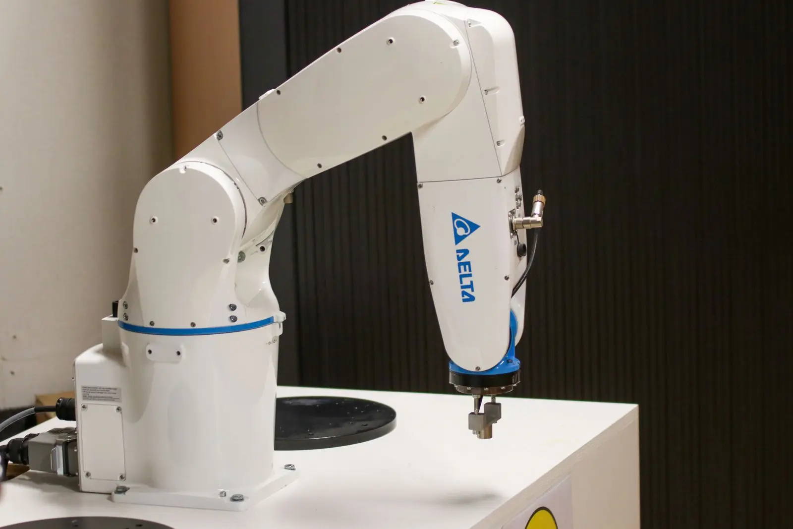
Robotic press tending
Automate blank presentation, loading, reorientation and formed-part removal with the end-of-arm tooling, press interface, cell controls and safeguarding engineered as one production system.
Direct answer
Robotic press tending uses an industrial robot or cobot to present material to a press, load it into the tooling, coordinate the press cycle and remove the formed component. Depending on the process, the robot may also reorient a part between bends, transfer it through several presses or place it into inspection and output storage.
The complete cell includes reliable blank presentation, application-specific gripping, press permissions and status signals, controls, safeguarding and a practical recovery sequence. Press motion and robot access must be treated as one coordinated system.
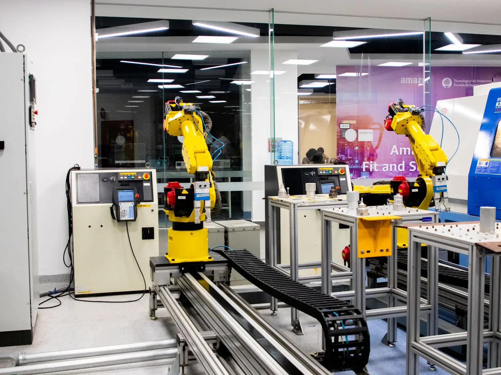
Press applications
The part behaviour, tooling and required operator access determine whether a robot or cobot concept is practical.
Pick sheet or fabricated blanks, support and locate them at the tooling, follow planned bends, regrip or reorient where required and stack completed parts.
Feed individual blanks or components, verify placement, remain clear during the cycle and remove good parts, rejects and scrap through controlled routes.
Move workpieces through one or more forming operations while controlling temperature, deformation, orientation and intermediate buffering.
Process comparison
| Design factor | Press brake | Stamping or forming press |
|---|---|---|
| Workpiece | Sheet or fabricated parts may become larger and harder to support after each bend. | Blanks or components may be smaller, faster cycling or transferred between several tools. |
| Robot task | Load, support, follow, reorient and remove through a planned bend sequence. | Load, verify, clear, unload and transfer while matching the press cycle. |
| End-of-arm tooling | Often vacuum or mechanical tooling with sufficient reach, support and controlled regrip. | Mechanical, vacuum or magnetic gripping selected for oil, edges, temperature and cycle duty. |
| Presentation | Sheet stacks, racks or locating tables with separation and double-blank control where needed. | Trays, conveyors, feeders, destackers or vision-guided picking matched to part orientation. |
| Key proof | Part support and robot reach across every bend without collision or unacceptable deflection. | Reliable placement, robot-clear confirmation and safe coordination with every press state. |
Safe process handshake
Robot entry, press movement, tooling state and access permissions are coordinated through defined signals and safety functions. The risk assessment covers normal production as well as setup, replenishment, tool changes, cleaning, jam clearance and fault recovery.
A collaborative robot does not automatically make press tending a collaborative application. Sheet edges, grippers, trapping points, moving tooling and the formed component can still require guarding, scanners or controlled access.
Confirm the press is in the defined safe loading state before the robot enters.
Prove the blank or component is present and correctly located where required.
Confirm the robot and tooling have left the hazardous process envelope.
Guide authorised operators through a safe reset after an interruption or misfeed.
Feasibility checklist
| Provide | What we need to understand | Why it changes the concept |
|---|---|---|
| Part drawings and samples | Raw and formed geometry, material, mass, surface, sharp edges, deformation and variants. | Determines gripping, support, reorientation and presentation. |
| Press and tooling details | Make, model, tooling layout, opening, stroke, operating modes and available interfaces. | Defines access, permissions, control integration and safe states. |
| Timed operator sequence | Every load, bend, regrip, unload, inspection and stacking step. | Shows whether the robot meets the required production cycle. |
| Layout and access | Floor space, material route, guarding, operator positions and tool-change access. | Sets robot reach, presentation position and safeguarding architecture. |
| Output and changeover | Batch sizes, variants, shift pattern, target output and change frequency. | Tests the business case and the value of recipes or quick-change tooling. |
Build the commercial case using the machine-tending ROI framework.
Frequently asked questions
It can where payload, reach, part support, bend sequence and cycle time are suitable. The complete application still requires risk assessment, and hazards from the press, sheet edges, gripper and trapping points may require safeguarding even when a collaborative robot is used.
Often yes when the press has suitable access, controllable operating states, a defined safe stop and usable interface signals. Additional sensing, control logic and safeguarding may be required. Review the existing-machine retrofit checklist.
Potentially. The robot must support, reorient and present the changing component accurately at each step without colliding with the tooling or exceeding reach and payload limits. The complete bend sequence should be simulated and trialled.
Options include located stacks, racks, trays, conveyors, feeders, destackers and vision-guided picking. The method must prevent double picking and give the robot a repeatable orientation while providing the required production capacity.
Send part drawings and weights, samples if available, press and tooling details, the timed operator sequence, batch sizes, output target, floor-space information and a video showing the current process and access.
Start with the forming sequence
We will use the real process to identify the likely robot, end-of-arm tooling, presentation, interfaces and safety architecture.