Insert and preform loading
Present, orient and verify inserts, labels or preforms before placing them accurately into the mould tool.

Injection moulding automation
Automate insert placement, moulded-part removal, runner separation, inspection and transfer with the gripper, machine handshake, cell control and safeguarding designed around the moulding process.
Direct answer
Injection moulding machine tending uses a robot to interact with the moulding cycle. It can place inserts or preforms before the mould closes, remove components after mould opening and transfer good parts to cooling, degating, inspection, assembly or packing.
The correct solution depends on the mould, component, cycle window and downstream task. A production-ready cell includes application-specific end-of-arm tooling, machine permissions and feedback, part or insert sensing, quality routing, safe access and recovery after an interrupted cycle.
Application scope
Present, orient and verify inserts, labels or preforms before placing them accurately into the mould tool.
Grip or receive moulded parts and runners within the available mould-open time without marking or deforming the product.
Cool, separate, trim, inspect, assemble, mark, count or transfer accepted parts to controlled packing and rejected parts to quarantine.
Automatic cycle
| Stage | Robot operation | Typical conditions to prove |
|---|---|---|
| Prepare | Collect and orient any insert, label or preform needed for the next shot. | Correct recipe, insert available, orientation confirmed and end-of-arm tooling ready. |
| Permit entry | Enter only when the moulding machine is in the agreed safe access state. | Mould open, process motion safe, ejector or cores in the required position and robot permission active. |
| Place or remove | Load inserts and remove the moulded component, runner or both. | Insert seated or component grip confirmed before the robot withdraws. |
| Prove clear | Leave the mould area and signal that the process envelope is clear. | Robot-clear state, tooling clear and all required part checks passed. |
| Route output | Transfer the component to cooling, trimming, inspection, assembly or packing. | Good, reject or hold result and a confirmed downstream destination. |
| Recover | Stop predictably and guide an authorised response after a mis-pick or interrupted cycle. | Known machine and robot states, controlled access and a validated restart sequence. |
Robot and tooling selection
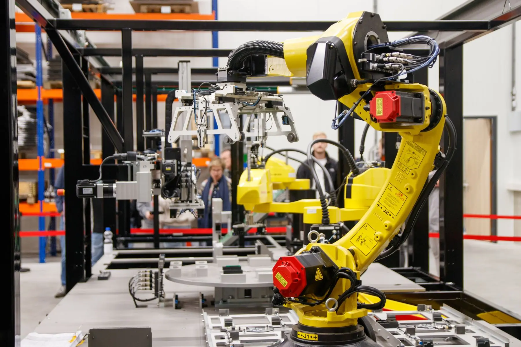
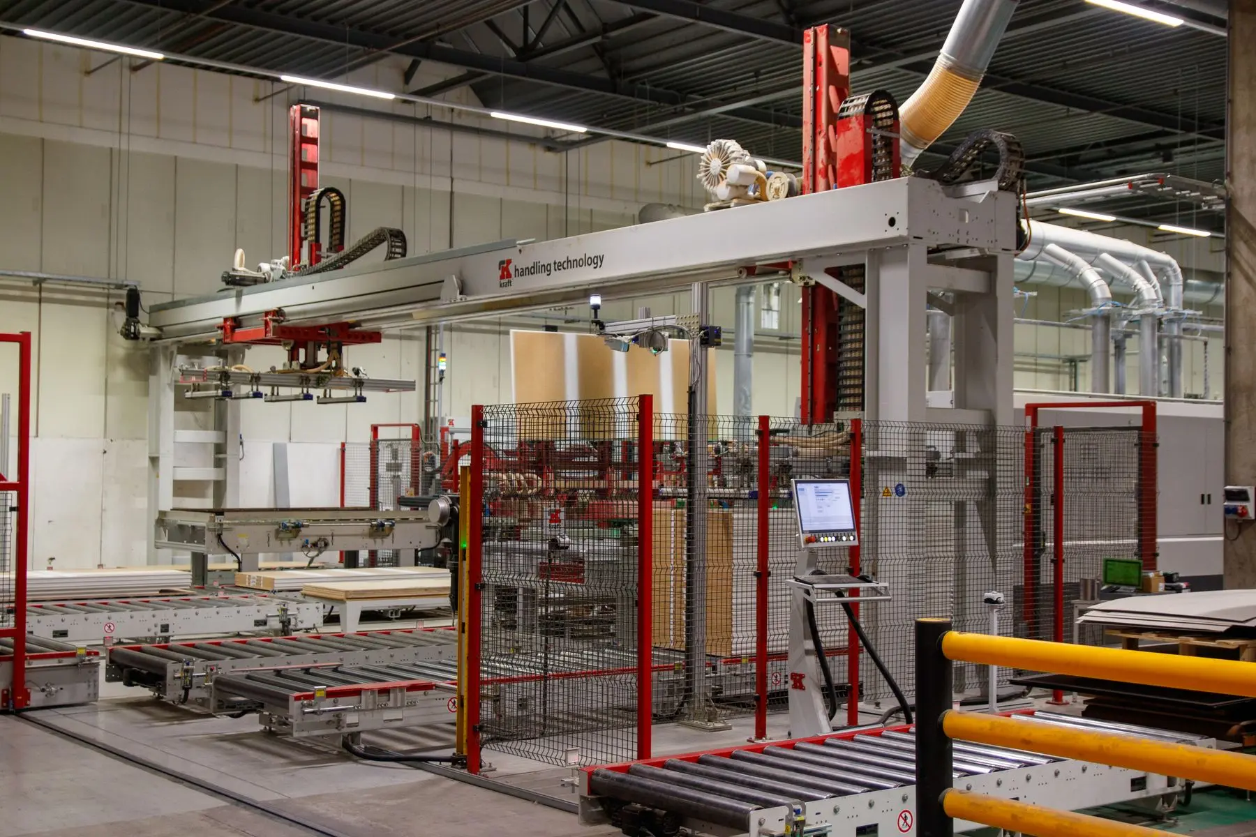
A top-entry linear take-out robot may suit a fast, repeatable removal task. A six-axis industrial robot can add orientation changes and linked secondary operations. A cobot may suit selected lower-speed processes with frequent operator interaction, but the moulding machine, tooling, hot material and trapping hazards still determine the safeguarding.
End-of-arm tooling must handle the actual moulded condition. Temperature, softness, surface finish, draft, runner attachment, static and deformation can all change the grip method and how soon the component may be placed onto a conveyor or fixture.
Select mechanical, vacuum or compliant tooling around the real released component.
Confirm inserts, parts, runners and tooling condition where the process requires it.
Avoid marks and deformation while controlling hot, sharp or unstable components.
Use recipes, replaceable fingers or tool change where the mould and product range justify it.
Feasibility checklist
| Project input | Details to provide | What it determines |
|---|---|---|
| Moulding machine | Make, model, clamp arrangement, opening, controller, existing robot interface and operating modes. | Access, machine handshake, mounting and integration approach. |
| Mould and component | Cavity count, inserts, part and runner geometry, weight, temperature, surfaces and release behaviour. | Robot payload, reach, end-of-arm tooling and cycle risk. |
| Cycle evidence | Mould-open window, removal time, current operator steps, faults and target cycle. | Robot performance and whether added operations fit without extending production time. |
| Product matrix | Every mould, component and insert expected to use the cell, with changeover frequency. | Recipes, tooling changes, presentation and validation scope. |
| Downstream process | Cooling, runner removal, inspection, assembly, marking, counting, packing and reject rules. | Cell layout, secondary tooling, controls and output handling. |
| Site constraints | Floor space, guarding, services, maintenance access and required operator tasks. | Robot architecture, safe access and installation plan. |
Check the requirements for integrating with an existing production machine.
Frequently asked questions
Yes where each insert can be presented, gripped, oriented and seated repeatably within the available cycle. The cell may use mechanical location, sensors or vision to confirm that the correct insert is present before mould closing is permitted.
Often yes when the machine provides suitable physical access, defined safe states and a usable interface for robot permissions and cycle status. The moulds, ejector or core sequence, guarding and retained manual operation must also be assessed.
A linear robot can suit fast, dedicated vertical removal. A six-axis robot offers more freedom for insert loading, reorientation and secondary operations. The required cycle, reach, payload, floor space, product range and downstream work determine the better architecture.
It can when the end-of-arm tooling, grip force, contact surface and release timing are designed around the actual material condition. Cooling fixtures or conveyors may be needed before inspection, assembly or packing.
Yes where the required checks and packing sequence can be automated reliably. Options include vision inspection, gauging, reject separation, counting, orientation, tray loading and transfer to a packaging process.
Provide moulding-machine and controller details, mould and component drawings, samples, cycle times, cavity and insert information, the current operator sequence, downstream requirements, product variants, floor space and a process video.
Start with the mould and released component
We will identify the likely robot architecture, end-of-arm tooling, machine interface, presentation, quality checks and safe operating concept.