Consider a cobot when
The application needs a compact, flexible layout, moderate handling speed and frequent operator-led changeovers. The complete cell still requires a task-specific risk assessment.

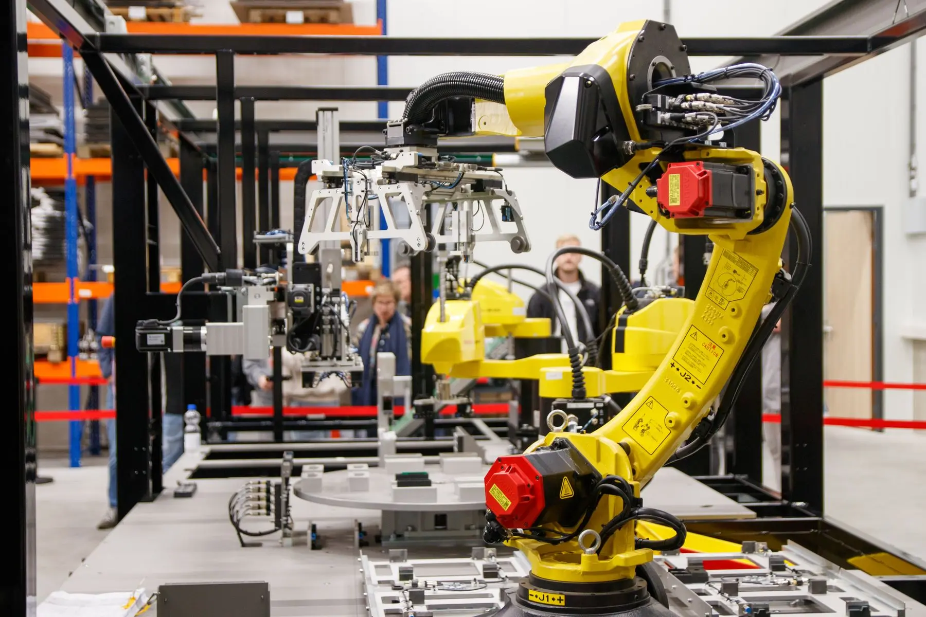
CNC lathe robot loading UK
Oxford Industrial Automation designs and integrates robot and cobot tending cells for CNC lathes and turning centres—from raw-part presentation and dual grippers to automatic doors, chuck signals, gauging and safe recovery.
Direct answer
CNC lathe robot loading uses a robot or cobot to collect a raw component, open the machine, operate the chuck or collet, load and seat the part, start the turning cycle, then unload and route the finished component. The cell exchanges permissive and status signals with the lathe so each movement happens in a defined sequence.
A complete system also addresses the difficult details: separating raw and finished parts, gripping changing diameters, preventing double loading, clearing coolant and swarf, proving chuck state, reversing a part for a second operation and recovering safely from a stopped cycle.
Oxford Industrial Automation integrates the robot, end-of-arm tooling, part buffer, machine interface, guarding and operator controls as one production system—not as separate pieces of equipment.
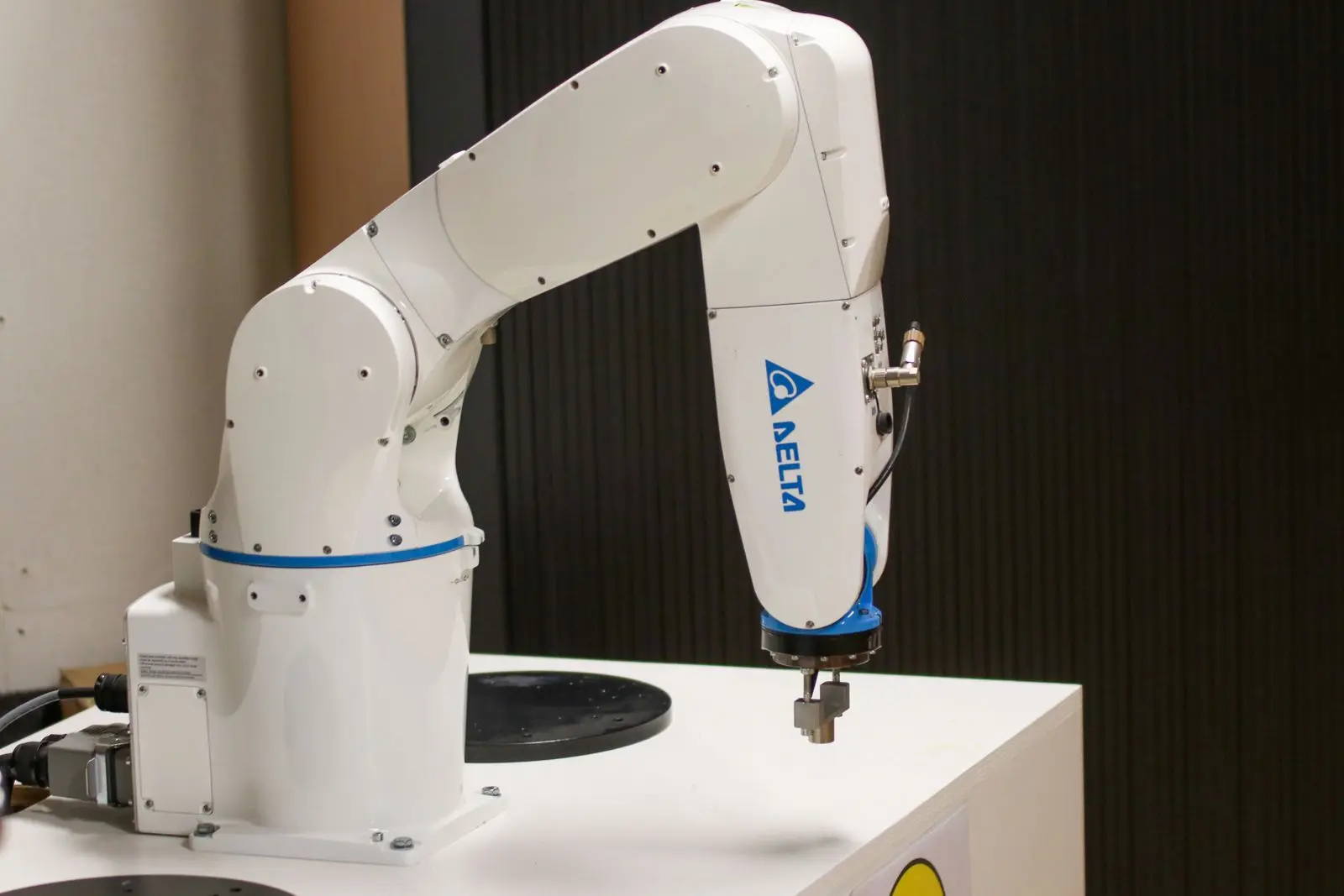
Lathe automation checklist
The best candidates have a repeatable machining cycle, accessible workholding and enough recurring production to justify the changeover. A site assessment turns these questions into a measured cell concept.
| Check | What we need to establish | Why it affects the cell |
|---|---|---|
| Part family | Raw and finished diameters, length, mass, variants, gripping surfaces and allowable marks. | Sets payload, gripper stroke, finger design and changeover method. |
| Chuck or collet | How it opens, closes and confirms its state; whether jaw pressure or part seating must be monitored. | Prevents the robot entering an unsafe or uncertain loading sequence. |
| Machine access | Door aperture, spindle centreline, turret position, robot approach and retained manual access. | Determines reach, cell layout, guarding and whether a robot or cobot fits. |
| Cycle stability | Turning time, tool life, chip behaviour, coolant, stoppages and inspection frequency. | Reveals the real unattended limit and the exceptions an operator must manage. |
| Capacity target | Required parts per shift, current manual exchange time and desired unattended duration. | Sizes trays, drawers, conveyors and finished-part storage. |
| Control interface | Available I/O, cycle start, door status, chuck status, programme selection and fault signals. | Defines a robust handshake instead of relying on timing assumptions. |
Automatic turning cycle
The precise cycle depends on your lathe and component, but reliable cells follow the same controlled logic.
Supply the correct blank in a known position using trays, drawers, pallets, conveyors or vision-assisted picking.
Open the door, remove the finished part, clear the workholding and insert the next blank—often with a dual gripper.
Confirm component position, close the chuck or collet, prove the workholding state and clear the robot from the machine.
Start the verified CNC programme, then send the completed part to output, gauging, cleaning or a second operation.
Built around your lathe
The robot is only one part of the solution. Reliable production depends on the interfaces around it and on simple recovery for the people who operate the cell.
For an existing machine, we assess what can be retained and what needs modification. Read the broader machine-tending retrofit guide for automatic-door, workholding and control considerations.
| Cell element | Typical lathe-specific scope |
|---|---|
| Part presentation | Machined trays, drawers, pallets, conveyors or guided picking sized for the target production window. |
| End-of-arm tooling | Single or dual grippers, interchangeable fingers, grip confirmation, blow-off and protection for finished surfaces. |
| Lathe automation | Automatic door, chuck or collet operation, cycle start, programme selection and status or fault signals. |
| Process support | Swarf and coolant control, part reversal, gauging, marking, cleaning, reject routing or transfer to operation two. |
| Controls | PLC, HMI, part recipes, guided recovery, alarms, production counts and defined operator modes. |
| Safety | Risk assessment, guarding, interlocks, scanners where appropriate, safe stopping and validated access modes. |
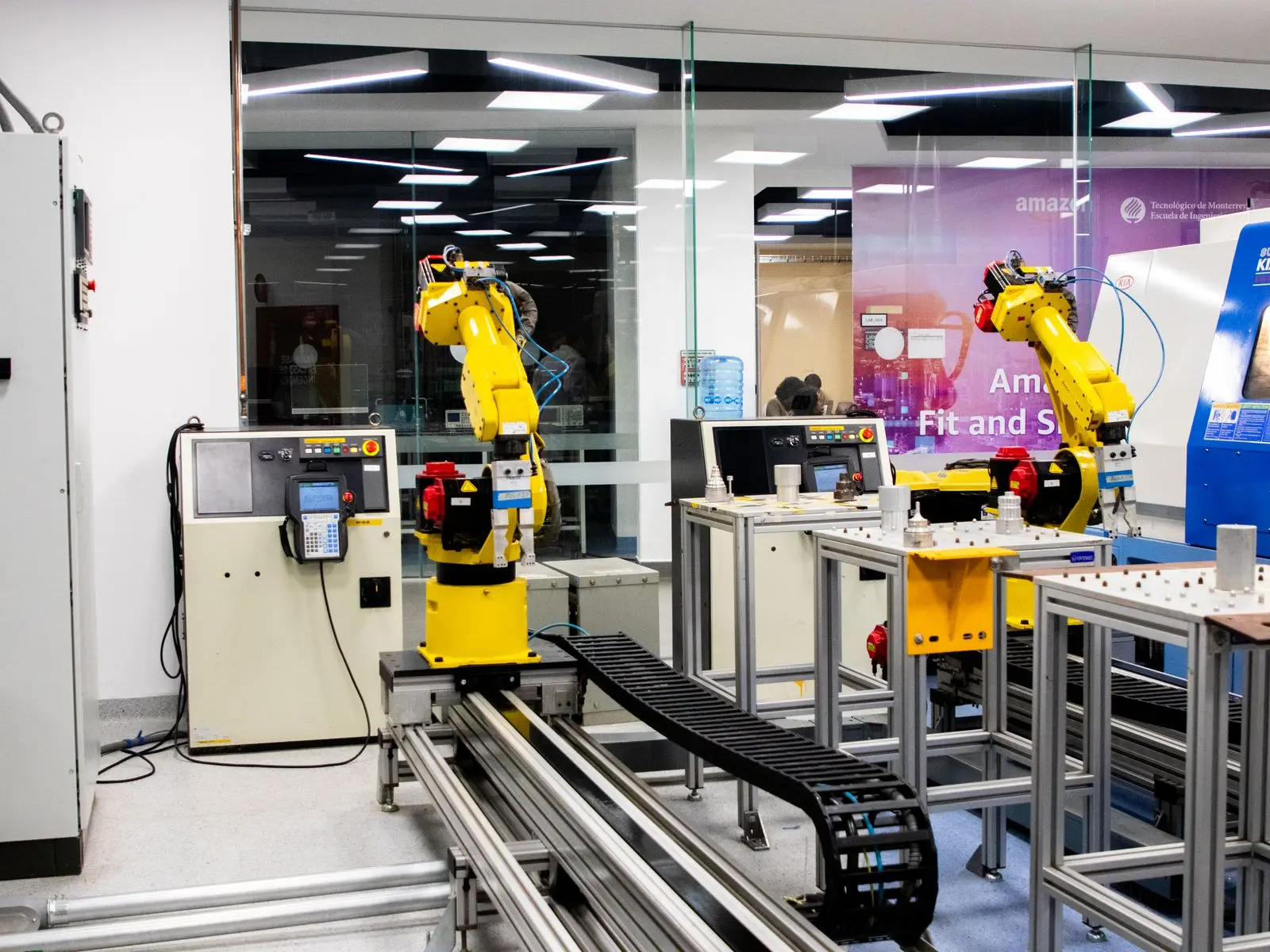
Production realities
They are treated as design inputs, not commissioning surprises. The concept review records likely chip forms, coolant carry-out, jaw contamination and the different surfaces available before and after machining.
Air blow-off, drainage time, angled part handling, chuck cleaning and grip confirmation can be added where the process needs them. Dual grippers shorten the door-open exchange, while separate raw and finished fingers can protect critical surfaces or accommodate a diameter change.
If the part must be turned at both ends, the cell can include a regrip station, turnover device or a second machine. The right arrangement depends on datum control, takt time, inspection needs and whether work-in-progress between operations is acceptable.
Choose the right automation
Neither is automatically the better choice. The decision follows from payload, reach, exchange time, access, replenishment and the safeguarding needed for the complete application.
The application needs a compact, flexible layout, moderate handling speed and frequent operator-led changeovers. The complete cell still requires a task-specific risk assessment.
Fast exchanges, heavier parts, long unattended runs or a fully enclosed production cell matter more than open collaboration.
Compare productive output and operator involvement—not robot speed alone. Include replenishment, gauging, tool changes and fault recovery.
For a fuller comparison, see our cobot machine tending guide. For the wider application family, return to CNC machine tending systems.
Prepare a useful enquiry
You do not need a finished specification. These six items let us test feasibility and identify the next engineering question quickly.
Lathe make, model, control, age, chuck or collet type and any existing automatic-door equipment.
Drawings or dimensions, material, mass, raw stock form, finished surfaces, variants and typical batch size.
Turning time, manual unload/load time, output by shift, inspection steps, tool intervention and common stoppages.
A safe recording of the operator cycle showing door, chuck, part handling and available floor space.
Required output, desired unattended duration, shift pattern and the operational problem you want to remove.
Cell footprint, access routes, services, loading frequency and any requirement to retain manual machine use.
Frequently asked questions
Often yes. We assess the door, chuck or collet, available control signals, safe stopping, robot access, part presentation and the stability of the turning process. Some machines need an automatic-door kit, workholding actuation or additional I/O before reliable tending is possible.
The cell needs a controlled way to open and confirm the door and to operate and confirm the chuck or collet. Existing automation may be usable; otherwise suitable actuators, valves, sensors and interfaces can form part of the retrofit.
Yes, where the component and datums allow it. The cell may use a regrip nest, turnover device, dual grippers or transfer to a second lathe. The method must preserve orientation, grip security and finished surfaces.
The design can use chuck blow-off, part drainage, angled handling and defined cleaning steps. The correct method depends on chip form, coolant volume, component geometry and how contamination affects part seating or gripping.
The limit is set by more than the number of blanks. Tool life, swarf, coolant, inspection, finished-part capacity and predictable fault recovery all matter. We size the buffer around a realistic production window and identify which interventions remain manual.
It can increase productive spindle time by reducing waiting and making exchanges consistent. The business case should use your measured cycle, demand, labour availability, scrap risk and planned operating hours. Our machine-tending ROI guide explains the inputs.
Scope can include the robot or cobot, grippers, part presentation, automatic door and chuck interfaces, PLC and HMI, guarding, risk assessment, installation, commissioning, operator training and production handover. The agreed proposal defines what is included for your machine and part family.
Page updated: 1 September 2026.
Start with your real cycle
Send the machine make and model, part drawing, cycle time, batch size and a short loading video. We will identify the first feasibility checks for your application.